Volver a la información general
Crossing with movable point EHZ HBS-HB
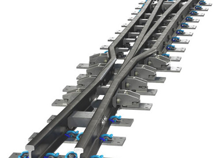
Common crossing with moveable point and splice rails "EHZ HBS-HB".
Volver a la información general
Common crossing with moveable point and splice rails "EHZ HBS-HB".

Crossings with moveable point and splice rails are used in order to avoid interruptions of the running edges. This may be required under the following circumstances:
Technical details:
Crossing vee:
The crossing vee is designed with a flexibly moveable point rail and splice rail. They are made from the corresponding thick web profile, which allows a direct thermit welding to the running rails. In the case of smaller geometries, both points are bolted elastically together to enable certain length compensation, which is necessary for the setting of the point. For larger geometries, point and splice rails are bolted together in a rigid way. To comply with highest safety requirements, the point and splice rails are additionally connected via a form-fitting safety plate.
Wing rails:
The wing rails are produced out of symmetrical rail profiles. Wing rails and the crossing vee are machined to ensure the switch process. By using a thick web rail, the bearing capacity is getting increased. By using symmetrical rail profiles, there is no need of a forged rail section and therefore no flash butt weld in the wing rails. The wing rails could be welded to the standard rails of the turnout directly. The thermal forces arising from the continuously welded track are transmitted from the crossing vee to the wing rails via solid distance blocks and finally deviated via fastening elements and sleepers.
Fastening of the crossing:
The complete crossing is positioned on individual plates and is indirectly fastened.
Setting and locking:
Depending on the geometry, setting is achieved via one or several setting points. Locking is done either via outside locks or motors with inside locks.